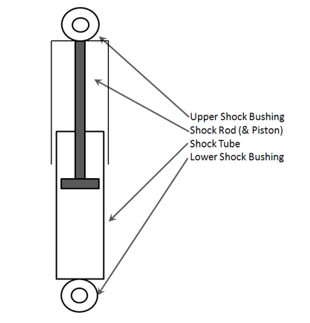
diagram shock absorber
Two types of valves are used in the shock absorber. SENSA-TRAC LOAD ADJUSTING SHOCK ABSORBERS Continued 58595 LS39 LS39 13000 20875 7875 60 P185 58598 LS74 LS74 14625 22125c 7500 VR None 58600 XP7 LS47.
Shock Absorber Systems
Cylinder C houses valve A and Valve B.
. A two-way valve A is attached to a rod G. Its upper eye is attached to the axle and the lower eye to the chassis frame. Diagram of shock absorber diagram of shock absorber.
Diagram Parts Of A Shock Absorber February 29 2016 Gary Diagram Parts Of A Shock Absorber 9 out of 10 based on 274 ratings. It does this by. Chrysler 300 diagram suspension rear mirror wiring.
A simplified diagram of the telescopic shock absorber. Schematic diagram of shock absorber Source publication Resistance Force of a Shock Absorber Using Magnetic Functional Fluids Containing both Micrometer-sized and Nanometer-sized. An anchor snubber is a bridle used to take.
CylinderC is surrounded by outer tube D. Computation of remaining useful life on a physic-based model and impact of a prognosis on the maintenance. Essentially shock absorbers are devices that smooth out an impulse experienced by a vehicle.
Which System On An Automobile Uses Shock. Download scientific diagram Diagram of the shock absorber. Engineering print material Maker.
A shock absorber is a mechanical device that is designed to absorb and dampen the shocks and vibrations that are created by the suspension system of a vehicle. 1 intake valves and 2 control valves. The intake valves are basically check valves which provide only slight resistance to flow in one.
S is shock absorber stroke which is the value we are trying to find. Shock absorbers are a critical part of a suspension system connecting the vehicle to its wheels. Given that the kinetic energy capacity of the shock absorber and tire must be equal to the total energy Eq.
A shock absorber in reality a shock damper is a mechanical or hydraulic device designed to absorb and damp. The assembly consist of sheet metal body which cover with piston and cylinder. Shock absorber - Explained and animated 3d A shock absorber in reality a shock damper is a mechanical or hydraulic device designed to absorb and damp shock impulses.
Car Absorber Diagram 9 out of 10 based on 375 ratings.

Shock Absorber Working Principle Download High Quality Scientific Diagram
A Schematic Diagram Of The Macpherson Suspension System 1o4 Car Model Download Scientific Diagram
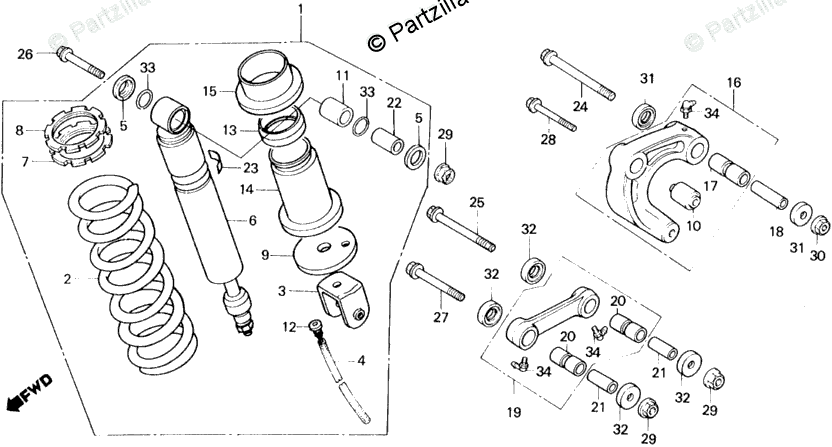
Honda Motorcycle 1986 Oem Parts Diagram For Shock Absorber Partzilla Com

Shock Absorber Wikipedia
Superpro Suspension Parts And Poly Bushings Forford Australia Falcon 1964 1966 Xm Xp Xm 90 01 64 01 65
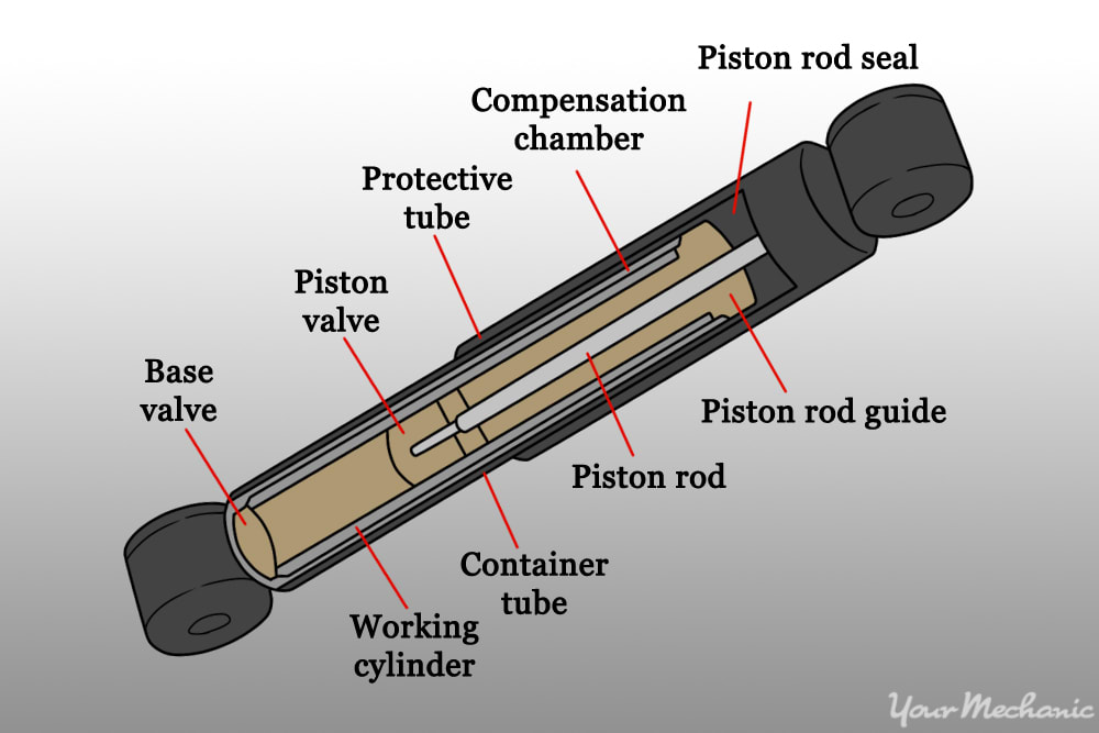
How To Replace Shock Absorbers Yourmechanic Advice
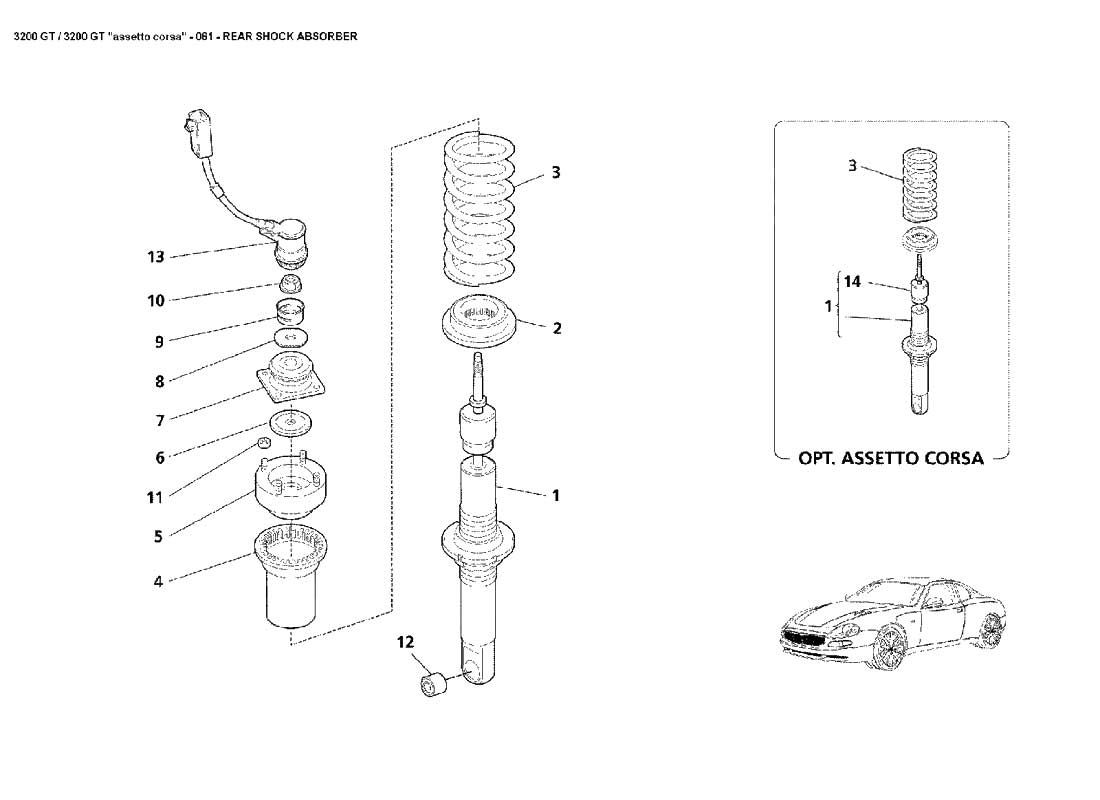
Diagram Rear Shock Absorber 061 Ferrparts

Shock Absorber S Klr650 2017 Parts Diagrams Kawasaki Parts Kuala Lumpur Kl Malaysia Selangor Dealer Supplier
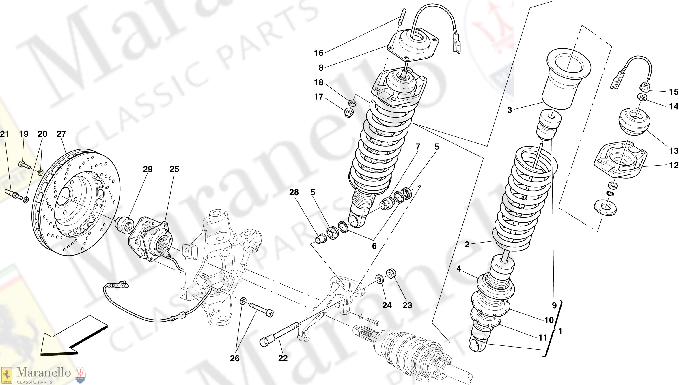
056 Rear Suspension Shock Absorber And Brake Disc Parts Diagram For Ferrari 612 Scaglietti Maranello Classic Parts

Suspension Diagram Mx 5 Miata Forum
Information Precautions Shock Absorbers

Shock Absorber An Overview Sciencedirect Topics

Air Suspension System Diagram Parts Working Types Advantages

Design Modeling And Analysis Of A Novel Hydraulic Energy Regenerative Shock Absorber For Vehicle Suspension

Shock Absorber Definition Functions Components Types Studentlesson

Adjustable Monotube Shock Absorber Diagram Schematic And Image 03

Spring And Shock Absorber Specs Truck